
BIM 3D Model: Components, Uses and How It Works
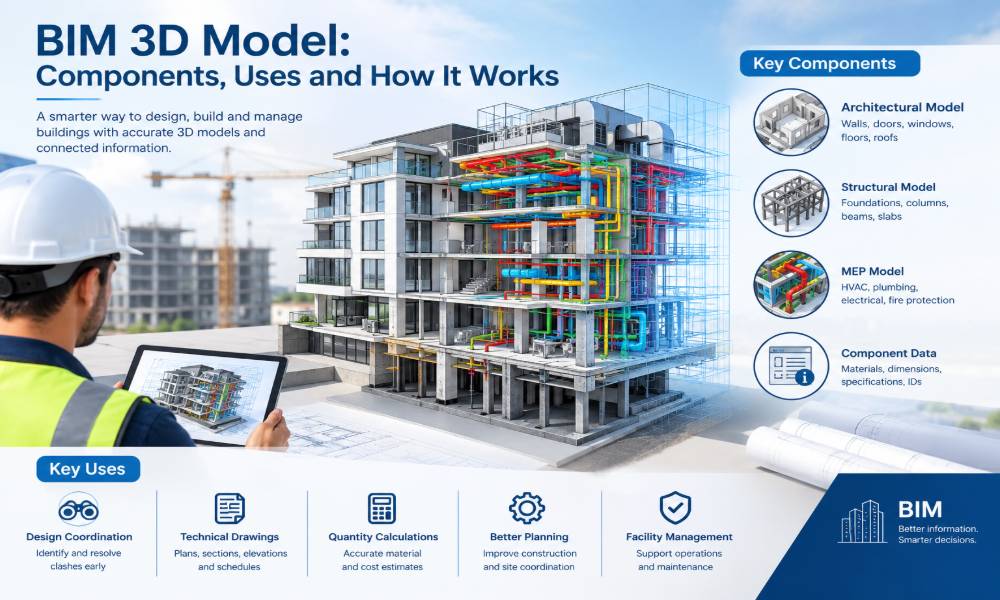
A building project involves architectural drawings, structural details, mechanical systems, electrical layouts and plumbing plans. Each discipline has its own requirements, but all these elements must fit together within the same building.
A BIM 3D model brings this information into a shared digital model. Architects, engineers and contractors can examine building components in three dimensions, check their positions and review how different systems interact before work reaches the construction site.
The usefulness of a BIM model depends on the information it contains, the accuracy of the source data and the level of detail required for the project.
What Is a BIM 3D Model?
A BIM 3D model combines a building’s three-dimensional geometry with information about its components, including walls, columns, pipes and ducts. Each element can contain details such as dimensions, materials and specifications. Unlike a basic 3D model, BIM supports design documentation, coordination and quantity calculations. It also helps architects, engineers and contractors review how different building systems fit together. The model can be updated as project designs change, keeping relevant information aligned throughout the construction process.
BIM 3D Model vs Traditional 3D Model
A traditional 3D model is often created to represent a building’s appearance, shape or spatial arrangement. A BIM model is developed with additional information about the building elements and their relationships.
The difference becomes important when the model is used for engineering and construction work.
- Geometry: Both models can represent buildings in three dimensions, but BIM elements are organised as identifiable building components.
- Component properties: BIM objects can contain dimensions, materials, classifications and specifications.
- Technical drawings: BIM software can generate plans, sections, elevations and schedules from model information.
- Design coordination: Separate architectural, structural and MEP models can be reviewed together to identify potential conflicts.
- Quantity calculations: Selected model elements can provide quantities for estimating and planning, subject to model quality and measurement rules.
- Information management: Structured BIM data can be reused at different project stages when it is maintained and updated correctly.
A detailed 3D visualisation does not automatically qualify as a BIM model. The distinction lies in how the elements and their information are structured.
Main Components of a BIM 3D Model
The contents of a BIM model depend on the building type, design stage and project requirements. Most building projects involve three main modelling disciplines.
1. Architectural BIM Model
The architectural model represents the building layout and its physical arrangement. It commonly includes walls, doors, windows, floors, ceilings, roofs, staircases and façade elements.
Architects use this information to review room layouts, dimensions, openings and circulation areas. Other disciplines can refer to the same model when planning structural elements and building services.
2. Structural BIM Model
The structural model represents the main elements that form the building’s structural system.
These may include foundations, columns, beams, slabs, structural walls and other load-bearing components.
When the structural model is coordinated with the architectural design, the team can check slab openings, beam positions, column locations and other interfaces that affect installation and construction.
The model represents the agreed engineering design; it does not replace structural analysis or engineering approval.
3. MEP BIM Model
MEP modelling covers the mechanical, electrical and plumbing systems installed within a building.
Depending on the project, the model may contain:
- HVAC ducts, equipment and ventilation routes
- Water supply and drainage pipes
- Electrical conduits and cable trays
- Fire protection pipework and equipment
- Plant-room equipment and service connections
- Vertical risers and ceiling service routes
MEP coordination is particularly important in ceiling voids, service shafts and plant rooms. Several systems may need to occupy the same limited space, making it necessary to check clearances and installation access before work begins.
4. Component Data and Properties
A BIM model can also hold information associated with individual building elements. This may include material type, dimensions, equipment identifiers, manufacturer details, classification codes and maintenance information.
Not every project needs every property. The modelling requirements should specify which information is necessary for design, construction or handover.
How Is a BIM 3D Model Developed?
The BIM modelling process varies depending on whether the team is working from a new design or documenting an existing building. The main stages generally follow a defined sequence.
Step 1: Review the Project Requirements
Before modelling starts, the team establishes the purpose of the model, the required level of development, coordinate requirements, software formats and final deliverables.
The project specification should also identify which building elements need to be modelled and what information each element must contain.
These decisions help control modelling time and prevent the delivery of a model that is too basic or unnecessarily detailed for its intended use.
Step 2: Collect Drawings and Survey Data
For a new development, the source information may include architectural drawings, structural calculations, MEP layouts and design specifications.
For an existing building, the available drawings may not reflect later alterations or actual site dimensions. A measured building survey or 3D laser scanning can help establish the existing conditions.
Laser scanning captures measurements from building surfaces. After processing and registration, the resulting point cloud can be used as a reference for developing the BIM model.
The source data should be checked for missing information, inconsistent dimensions and coordinate differences before modelling proceeds.
Step 3: Build the 3D Geometry
The modelling team creates the required building components using suitable BIM software.
Walls, slabs, columns, openings, ducts and pipes are positioned according to the approved design or measured site information. Their dimensions and properties are developed to suit the intended use of the model.
Existing buildings may require additional attention because actual conditions can differ from the original drawings. Irregular surfaces, relocated services and undocumented alterations may need to be accounted for during modelling.
Step 4: Add Information to Model Elements
Once the main geometry is established, the relevant properties are assigned to individual components.
For example, an equipment object may contain an identifier, equipment type and selected technical specifications. A wall may contain material and thickness information.
The aim is to provide the information required by the project team without adding data that has no practical purpose.
Step 5: Coordinate the Building Disciplines
Architectural, structural and MEP models are combined or referenced together for coordination, where required.
The team checks whether ducts intersect beams, whether pipework conflicts with cable trays and whether equipment has sufficient clearance for installation and maintenance.
Clash detection software can identify potential geometric conflicts, but the results need to be reviewed. Some intersections are intentional, while other design problems may not appear as simple geometric clashes.
Step 6: Check and Issue the Model
Before delivery, the model is reviewed against the agreed requirements.
Checks may cover dimensions, coordinates, component properties, drawing references, model alignment and the completeness of the required elements.
The final deliverables depend on the project agreement and may include native BIM files, IFC exports, coordinated drawings, schedules and model views.
The issued model should clearly reflect its intended purpose and verification status.
What Does LOD Mean in BIM Modelling?
LOD stands for Level of Development in commonly used BIM terminology. It describes how developed and reliable model elements are for specific project uses.
The required level depends on the design stage, construction requirements and information exchange standards agreed by the project team.
- LOD 200: Elements have approximate geometry and general information suitable for certain early-stage design tasks.
- LOD 300: Elements have defined geometry and information appropriate to the agreed design and documentation requirements.
- LOD 350: Additional interfaces and relationships with adjacent systems are represented where required.
- LOD 400: Elements contain more developed information to support fabrication and installation.
- LOD 500: Elements represent verified existing or installed conditions, with the verification scope defined by the project requirements.
These levels should not be treated as a universal guarantee of dimensional accuracy. A model’s actual reliability depends on its source information, modelling rules and verification process.
For this reason, the required LOD should be established before modelling begins, particularly when the model will be used for construction coordination or fabrication.
Practical Uses of a BIM 3D Model
BIM 3D modelling is used for different purposes throughout a building project. Its value depends on the quality of the model and the way the project team uses it.
Design Review
Architects and engineers can review building layouts, room dimensions, structural arrangements and service routes within a shared three-dimensional environment.
Sections and model views can also help explain design details that may be difficult to interpret from separate drawings.
Construction Coordination
Contractors can use a coordinated BIM model to review the position of structural components, service installations, access routes and equipment.
This is useful when multiple trades are working in the same area and need to confirm that their installations fit within the available space.
Clash Detection
Clash detection checks model elements for potential spatial conflicts.
For example, an HVAC duct may cross a structural beam, or a drainage pipe may interfere with an electrical containment route. Identifying these issues during design coordination allows the relevant teams to review the arrangement before installation.
The results are only as reliable as the models being checked. Missing elements, outdated files and incorrect coordinates can affect the outcome.
Quantity Take-Off
A BIM model can provide quantities for selected elements, including floor areas, wall areas, concrete volumes and equipment counts.
These quantities can support estimation and construction planning. However, the team must check how the elements are modelled, which components are included and which measurement rules apply before using the results for pricing or contractual purposes.
Renovation and Existing-Building Projects
For refurbishment projects, a BIM model can represent the existing structure and provide a reference for proposed modifications.
Where the original drawings are incomplete, survey measurements and point-cloud data can help the modelling team document actual site conditions.
Facility Management
A BIM model may also support building operations when it contains the required asset information. Equipment references, selected specifications and maintenance-related data can help facility teams locate and manage building assets.
A design model is not automatically ready for facility management. The required asset data must be collected, checked and handed over in an agreed format.
Software Used for BIM 3D Modelling
The software selected for a BIM project depends on the type of building, the modelling discipline and the required deliverables.
Autodesk Revit is widely used for architectural, structural and MEP BIM modelling. It supports the creation of building elements with associated properties and the production of coordinated documentation.
Autodesk Navisworks is commonly used to combine models from different disciplines, review coordination issues and run clash detection.
Autodesk Civil 3D supports civil engineering and infrastructure design workflows that may need to interface with building models.
Point-cloud processing software is also used when existing site conditions have been captured through 3D laser scanning.
The choice of software should reflect the project team’s requirements, file compatibility and information exchange standards. Software alone does not determine the accuracy of the final model.
What Affects BIM 3D Model Accuracy?
A BIM model can only represent conditions as reliably as the available information and modelling process allow. Several factors need attention.
Source drawing quality: Missing dimensions, outdated drawings and design revisions that have not been incorporated can lead to incorrect geometry.
Survey measurements: For existing buildings, measurement quality, control points, coordinate systems and point-cloud registration can affect how accurately the model represents the site.
Modelling tolerances: The required dimensional tolerance should match the intended use. A model for general design review may not meet the requirements for fabrication or installation.
Level of development: Elements modelled at a general level may not contain the details needed for more precise construction tasks.
Coordination between disciplines: Models must use consistent coordinates, levels and relevant design information to be reviewed together correctly.
Quality checks: Comparing model elements with approved drawings, survey data and project specifications helps identify discrepancies before issue.
A BIM model should therefore be checked against defined acceptance criteria rather than judged by its appearance alone.
BIM 3D Model vs Scan-to-BIM
BIM 3D modelling and Scan-to-BIM are related, but they do not describe the same thing.
A BIM 3D model is the structured digital representation of a building. It can be created from design drawings, engineering information or measured survey data.
Scan-to-BIM is a process used to develop a BIM model from reality-capture data, commonly obtained through 3D laser scanning.
The workflow generally includes:
- Capturing the building or site using suitable survey equipment.
- Registering the scans and processing the point-cloud data.
- Checking data coverage, alignment and quality.
- Modelling the required architectural, structural or MEP components.
- Comparing the model against the available measured data.
- Preparing the agreed model files and documentation.
A point cloud is not the same as a BIM model. It contains measured points representing visible surfaces, while a BIM model organises the relevant information into identifiable building components.
The amount of modelling required depends on the project. Some tasks need only selected building elements, while others require a more comprehensive representation of the existing structure.
Conclusion
A BIM 3D model connects building geometry with technical information that can be used for design review, construction coordination, quantity take-off and asset documentation.
The work begins with clear project requirements and suitable source information. The modelling team then develops the required elements, adds relevant properties, coordinates the different disciplines and checks the final deliverables.
For existing buildings, measured surveys and laser scanning can provide a reference for modelling actual conditions. The reliability of the result still depends on data quality, modelling tolerances and the checks carried out before delivery.
Understanding these requirements helps project teams choose the right BIM model for their design, construction or renovation work.
Need Survey Data for Your BIM Project?
Northern Engineering Surveys L.L.C. provides surveying and 3D laser scanning services that can support existing-condition documentation and BIM-related workflows. Accurate site measurements help project teams establish a reliable reference when working with existing buildings and structures.
Visit NES Dubai to learn more about its surveying and related services.
Frequently Asked Questions
1. What is a BIM 3D model used for?
A BIM 3D model can support design review, construction coordination, clash detection, quantity take-off and asset documentation. Its capabilities depend on the information included and the intended project use.
2. How is a BIM model different from a normal 3D model?
A normal 3D model may focus on the building’s shape and appearance. A BIM model also organises building components and their associated information for technical documentation and coordination.
3. Which software is commonly used for BIM modelling?
Autodesk Revit is widely used to create building BIM models, while Navisworks supports model coordination and clash detection. Other tools may be required for civil engineering and point-cloud processing.
4. What is LOD in a BIM 3D model?
LOD means Level of Development in commonly used BIM terminology. It describes how developed and reliable model elements are for their intended use. The required level should be defined in the project specification.
5. Can a BIM model be created from 3D laser scanning?
Yes. Laser scanning produces measured point-cloud data that can be used as a reference for developing a BIM model of an existing building. The final accuracy depends on the scan data, modelling requirements and verification process.
6. Does BIM clash detection prevent every construction conflict?
No. Clash detection helps identify potential spatial conflicts between model elements, but it cannot identify every design or site issue. Accurate source models, technical reviews and site verification remain necessary.