
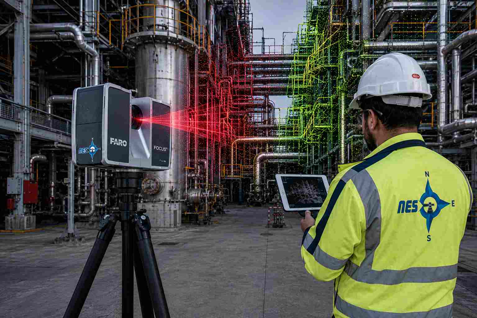
Surveying an operating plant is rarely a matter of simply setting up an instrument and taking measurements. Pipe racks overlap, equipment blocks sightlines, structural steel creates hidden areas, and some components are difficult or unsafe to reach.
This is where 3D laser scanning becomes particularly useful. Instead of measuring selected points manually, the scanner captures the surrounding geometry as a dense three-dimensional dataset. For plant projects, that data can be used to understand existing piping, equipment, structures and clearances before design or modification work begins.
The real challenge, however, is not simply scanning the plant. It is deciding where to scan, how to capture obstructed areas, how to control the data, and how to turn the point cloud into useful engineering information.
Planning Scan Positions Around Pipe Racks and Equipment
Plant layouts can change significantly from one area to another. An open yard may need relatively few scan positions, while a pipe corridor may require several overlapping setups.
A practical scan plan should consider:
- Review available plant drawings, previous survey data and site photographs before mobilisation.
- Identify pipe racks, vessels, platforms, structural steel and large equipment that may block scanner visibility.
- Position scanners from different directions rather than relying on a straight line of stations.
- Use elevated locations where possible to capture the upper levels of pipe racks and equipment.
- Increase scan coverage in congested areas where several pipes or structures overlap.
- Use mobile or handheld LiDAR where a tripod setup cannot efficiently cover narrow corridors or difficult access routes.
- Identify restricted areas, permit requirements and access windows before fieldwork starts.
The objective is not to use more scan stations everywhere. It is to place them where they provide the best visibility of the plant geometry.
Capturing Hidden Geometry in Congested Plant Areas
One of the biggest advantages of scanning a plant is the ability to capture complex geometry that would be difficult to document with individual measurements.
Pipework may pass behind vessels, below platforms or between multiple layers of structural steel. Equipment can also hide connections and clearances from normal viewing positions.
For these areas, survey teams can:
- Capture the same section from multiple angles to improve coverage.
- Use elevated scan positions for upper pipe runs and equipment connections.
- Combine static terrestrial scanning with mobile or handheld capture where appropriate.
- Pay particular attention to flanges, valves, supports, nozzles and instrument connections.
- Record surrounding structures at the same time so clearances can be checked later.
- Review difficult areas in the field before leaving the plant.
This approach helps reduce the number of assumptions that designers have to make when working with incomplete existing drawings.
Managing Occlusions and Shadow Zones
Occlusion is a major issue in plant scanning. A scanner can only measure what its laser can see. A large vessel may hide piping behind it, while closely packed pipework can create gaps between individual runs.
These areas need to be planned rather than discovered during modelling.
Common problem areas include:
- Behind storage and process vessels
- Under platforms and walkways
- Between closely spaced pipe runs
- Around equipment bases
- Behind structural columns
- Inside congested pipe racks
- Around partially enclosed machinery
Additional scan positions can be introduced to view these areas from another direction. Where complete visibility is not possible, survey teams can supplement the scan with photographs or targeted measurements.
A useful field practice is to review the developing point cloud before demobilisation. If an important connection or equipment area is missing, it is much easier to correct the problem while the survey team is still on site.
Combining Static and Mobile Scanning for Plant Coverage
No single scanning method is ideal for every part of a large process facility.
Static terrestrial scanners are well suited to areas where high geometric detail and controlled accuracy are required. Mobile and handheld systems can be useful for corridors, walkways and sections where repeatedly setting up a tripod would slow the survey.
A combined workflow can therefore be more practical:
- Static scanning for equipment, pipe connections and high-detail engineering areas.
- Mobile scanning for longer corridors and accessible plant routes.
- Handheld scanning for tight areas where tripod positioning is difficult.
- Survey control to provide a common reference between different datasets.
The important point is to select the scanning method according to the required accuracy, accessibility and engineering purpose rather than treating every area of the plant in the same way.
Establishing Survey Control Inside Industrial Facilities
A detailed point cloud still needs a reliable spatial reference before it can be used confidently for engineering work.
Plant surveys should be connected to the project’s established coordinate system through appropriate survey control. Depending on the project, this may involve GNSS observations, total station measurements and fixed control points.
Inside industrial facilities, satellite visibility can be limited by:
- Steel structures
- Pipe racks
- Buildings
- Tanks and vessels
- Covered areas
- Dense equipment
For this reason, total station observations can be particularly useful for transferring and checking control through the facility.
When mobile or SLAM-based scanning is used, the captured route should also be tied back to known control points. This provides an independent reference for checking accumulated positional drift.
Extracting Engineering Information From Plant Point Clouds
The point cloud itself is not always the final deliverable. For many plant projects, the important step is extracting engineering information from the captured geometry.
Depending on the required level of detail, the dataset can be used to identify:
- Pipe centre lines
- Pipe diameters
- Pipe elevations
- Valve locations
- Flange positions
- Equipment footprints
- Nozzle locations and orientations
- Structural members
- Equipment clearances
- Access and maintenance spaces
- Existing connections and tie-in locations
This information can then be compared with available engineering drawings.
A scan may reveal that an existing pipe has been rerouted, equipment has moved, or additional supports have been installed since the original drawings were prepared. Identifying these differences before design begins can prevent problems during fabrication and construction.
Comparing Scan Data With P&IDs and Existing Drawings
Existing plant documentation is not always an exact representation of current site conditions.
A useful application of the scan dataset is therefore to compare measured geometry with available documentation such as:
- P&IDs
- Piping isometrics
- Equipment drawings
- Structural drawings
- Previous as-built drawings
- Layout drawings
The point cloud provides the physical reference, while engineering documents provide design and process information.
When these sources do not agree, the difference can be investigated before a new design is issued. This is particularly important for brownfield modifications where new piping or equipment has to connect to an existing facility.
Using Plant Scan Data for Tie-Ins and Retrofit Projects
Plant modifications often depend on small details that are difficult to verify from drawings alone.
For a new tie-in, designers may need to know the exact position of an existing pipe, available clearance around the connection, nearby structural members and the location of surrounding equipment.
A detailed scan can provide this information before fabrication or construction begins.
The data can support:
- New pipe routing
- Equipment replacement
- Tie-in planning
- Structural modifications
- Expansion projects
- Shutdown preparation
- Access planning
- Clash checking
- Fabrication measurements
For retrofit work, this can be especially valuable because the existing facility may contain years of modifications that are not fully reflected in the original documentation.
Point Cloud Accuracy Verification Before Design Use
Plant scan data should be checked before it becomes the basis for engineering decisions.
Accuracy verification can include:
- Checking scan registration against survey control.
- Reviewing individual scan connections instead of relying only on the overall registration result.
- Checking critical equipment and pipe areas against independently measured points.
- Investigating sections where registration produces unexpected deviations.
- Re-scanning important areas where the captured geometry is incomplete or uncertain.
Critical engineering areas should receive more attention than open spaces where small geometric differences have little impact.
The purpose of verification is simple: the engineering team should know which parts of the dataset are measured and which areas require additional investigation.
From Plant Point Cloud to As-Built and 3D Models
Once the point cloud has been registered and verified, it can become the basis for several project deliverables.
Depending on project requirements, the data may support:
- As-built documentation
- 2D CAD drawings
- 3D plant models
- BIM models
- Piping layouts
- Equipment documentation
- Retrofit design
- Clash checking
- Future expansion planning
For larger facilities, retaining the original point cloud can also be useful after the immediate project is completed. Future engineering teams can return to the dataset to investigate existing conditions without immediately carrying out another full survey.
Why Plant-Specific Scanning Requires More Than Just a Scanner
Capturing a plant accurately is not simply a matter of placing a scanner in the middle of the facility.
The quality of the final result depends on the complete workflow, aligned with UAE industrial and standards regulation:
Site planning → scan positioning → control → data capture → coverage checks → registration → accuracy verification → engineering extraction
A scanner can collect millions of points, but those points only become useful when the survey is planned around the physical constraints of the facility and the requirements of the engineering team.
For congested plants, the most valuable result is not just a large point cloud. It is a reliable record of where the pipes, equipment and structures actually are, including the areas that are difficult to measure using conventional methods.
FAQs
What is 3D laser scanning used for in plant surveys?
It is used to capture detailed three-dimensional measurements of existing pipes, equipment, structures and surrounding spaces, particularly in congested or difficult-to-access plant areas.
Can laser scanning capture pipes behind equipment?
A scanner cannot capture geometry that is completely blocked from its line of sight. Multiple scan positions from different angles are therefore used to reduce occlusions and improve coverage.
Is mobile scanning suitable for plant surveys?
Mobile and handheld scanning can be useful for corridors, walkways and tight-access areas. For critical engineering measurements, it should be used within a controlled workflow and checked against established survey control.
Can plant scan data be used for retrofit projects?
Yes. Registered scan data can provide existing-condition information for equipment replacement, pipe routing, tie-ins, structural modifications and plant expansion.
What information can be extracted from a plant point cloud?
Depending on scan quality and project requirements, engineers can extract pipe geometry, elevations, equipment locations, nozzles, valves, structural elements and clearances.
Why is survey control important? Control provides a fixed spatial reference for the scan data. It allows the point cloud to be positioned correctly and provides an independent method for checking survey accuracy.
Need Accurate Plant Survey Data?
Northern Engineering Surveys L.L.C provides 3D laser scanning and industrial surveying support for plants, process facilities and brownfield projects. Our surveys capture existing piping, equipment, structures and congested areas with high-density spatial data.
When drawings are outdated or site access is restricted, LiDAR-based 3D laser scanning provides reliable as-built measurements for engineering design, retrofit planning, clash detection and plant modifications.