
3D Laser Scanning Inspection: Methods, Deviation Analysis and Verification
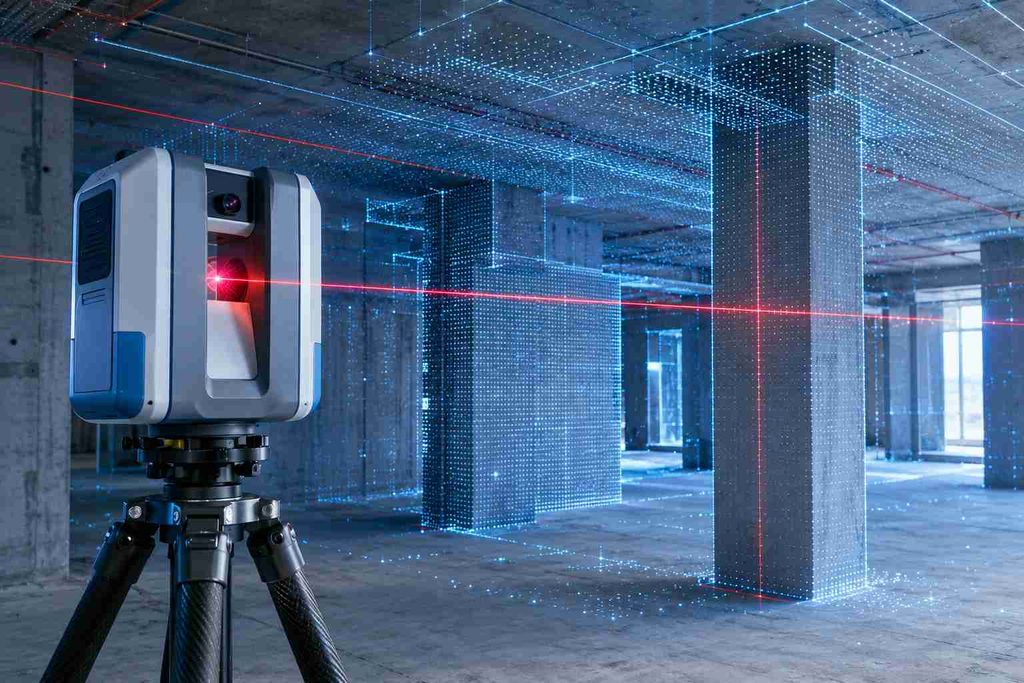
During construction, installation or renovation, the actual structure may differ from the original design. Changes in dimensions, alignment or surface levels can affect the quality of the finished work. These differences need to be checked carefully before the next stage of the project begins.
3D laser scanning inspection helps engineers measure existing structures and compare the results with design drawings or 3D models. The scanner captures millions of measurement points to create a detailed point cloud, allowing the team to examine dimensions, check alignment and identify areas that require further inspection. This gives project teams a clearer understanding of the actual site conditions and helps them make informed decisions during construction and quality control.
What Is 3D Laser Scanning Inspection?
3D laser scanning inspection uses a laser scanner to capture the shape and dimensions of an existing structure or component. The collected measurements form a 3D point cloud that shows the scanned object’s geometry.
Surveyors and engineers use this data to check measurements and compare actual site conditions with design drawings or 3D models.
Depending on the project, the inspection can help check:
- Dimensions of structural elements and installed components.
- Alignment and position of structures.
- Floor levels and surface variations.
- Clearances between equipment and nearby structures.
- Differences between actual construction and design drawings.
- Changes in a structure’s shape or position over time.
The inspection method depends on what needs to be measured. For example, checking a steel frame’s alignment requires a different approach from measuring variations in a concrete surface. Choosing the right scanning positions and analysis method helps produce useful results.
How the 3D Laser Scanning Inspection Process Works
A useful inspection starts with a clear understanding of what needs to be measured. Collecting scan data without defining the required checks can leave the team with a large point cloud but insufficient information to answer the original engineering question.
Defining the Inspection Scope
The survey team first identifies the structures or components to be checked and the measurements required. This may involve dimensions, alignment, elevations, clearances or comparison with an approved design model.
The team should also establish the required tolerance, reference coordinate system, site access arrangements and expected deliverables.
Capturing Site Measurements
The scanner is positioned at suitable locations to record the visible surfaces. Several positions may be needed to capture different sides of a structure and reduce gaps caused by columns, machinery or other obstructions.
Scan coverage matters because a surface that cannot be seen by the scanner cannot be measured directly. The team must plan the setup around the structure’s shape, accessibility and the level of detail required.
Processing and Aligning the Point Cloud
When measurements are collected from multiple scanner positions, the individual scans must be aligned to create a consistent dataset. This is known as point cloud registration.
The alignment may use overlapping geometry, surveyed control points or a combination of both. The processed data should be checked for registration errors, missing areas and unwanted points before measurements are taken.
Checking Dimensions and Geometry
Once the point cloud is ready, the inspection team measures the relevant features and compares them with the selected references.
Depending on the task, this may involve distances, elevations, angles, cross-sections, surface profiles or the position of individual components. If a design model is available, the software can be used to examine differences between the model and the scanned structure.
Preparing the Inspection Results
The final stage is to document the measurements in a format that the project team can review. This may include measurement tables, annotated views, cross-sections, deviation maps and a technical report.
Any difference outside the specified tolerance should be recorded for review. The scan identifies the measured condition; the responsible engineer determines its significance and the appropriate response.
Identifying Dimensional Deviations Using 3D Scan Data
A dimensional deviation is the difference between a measured value and its reference value. In a construction project, the reference may come from an approved drawing, a design model, a specified elevation or a previously verified measurement.
Laser scanning allows these differences to be examined across captured surfaces rather than at only a few isolated locations.
For example, an inspection of a concrete floor may show areas that sit above or below the intended elevation. A scan of a structural frame may reveal differences between the measured positions of its members and their designed positions.
The basic calculation is:
Deviation = Measured value − Reference value
A positive result means the measured value is greater than the reference, while a negative result means it is smaller. The meaning depends on the measurement direction and the coordinate system used.
For surface comparisons, inspection software can calculate the distance between the scanned points and a reference surface or model. These differences can then be displayed in a colour-coded deviation map.
The map helps the reviewer locate areas that need attention, but it does not determine acceptance by itself. Each result must be checked against the relevant project tolerance and the uncertainty of the measurement. A visible difference is not automatically a construction defect.
Checking Alignment, Position and Clearance From Point Cloud Data
A component can have the correct dimensions and still be installed in the wrong position. This is why inspection sometimes needs to consider the relationship between several elements rather than measuring each one separately.
A 3D point cloud provides a record of the visible geometry that can be used to examine these relationships.
Structural Alignment
Steel columns, beams and other structural members can be checked against their intended positions and orientations. Depending on the shape of the element, the analysis may use centre lines, planes, reference points or other geometric features.
The results help the project team understand whether the measured alignment falls within the specified tolerance.
Position of Installed Equipment
In industrial and building projects, the location of equipment, supports and connected components can affect subsequent installation work.
Scan data can be used to check the relative positions of visible elements and compare them with the available design information. If a component appears to be outside its intended position, further measurements or an engineering review may be needed.
Clearance Between Elements
Clearance checks are useful when existing structures must accommodate new equipment, services or other installations.
The scanned geometry can be compared with a proposed model to examine whether sufficient space is available. This can help identify potential clashes before installation begins, provided the relevant surfaces have been captured and the model is correctly aligned.
Laser scanning records visible geometry. It does not, on its own, confirm that equipment operates correctly or that a structure meets every structural or mechanical requirement.
Comparing Actual Geometry With Design Specifications
Approved drawings show the intended arrangement of a structure, but the completed work needs to be measured to establish what was actually built. Comparing scan data with design information provides a way to examine the differences.
The comparison is only meaningful when the correct design revision and coordinate reference are used.
Aligning the Scan With the Reference Model
The point cloud and design model must be brought into the same coordinate system before their geometry is compared. If they are incorrectly positioned or rotated relative to each other, the software may report differences that do not reflect the actual construction.
Where required, surveyed control points can help establish the relationship between the measured site data and the project reference system.
Reviewing Measured and Designed Dimensions
Once the datasets are aligned, the inspection can focus on the measurements relevant to the project. These may include:
- Differences between designed and measured elevations.
- Position and orientation of structural members.
- Distances between installed components.
- Surface profiles and cross-sectional dimensions.
- Potential clashes between existing structures and proposed installations.
The analysis should concentrate on the features that matter to the inspection rather than treating every point in the cloud as an equally important measurement.
Checking Against Project Tolerances
The measured differences must be assessed against the applicable specifications. The permitted variation for one element may not be suitable for another, so the relevant acceptance criteria need to be established in advance.
The review should also consider the quality of the scan, the alignment process and the accuracy of the reference information. Where a result falls outside the specified limits, the finding can be documented for further investigation.
Factors That Affect 3D Laser Scanning Inspection Results
The quality of an inspection depends on how the survey is planned, how the data is captured and how the measurements are processed. Several practical factors can affect the final results.
Scanner Position and Visibility
A scanner can only measure surfaces that are visible from its position. Machinery, columns, temporary structures and tightly spaced components may block parts of the inspection area.
Additional scan positions can help capture surfaces that would otherwise be missed. The required coverage should be considered before the team leaves the site.
Surface Conditions
Reflective, transparent, very dark or highly absorptive surfaces can affect measurement quality, depending on the scanner and the surrounding conditions.
Where the surface is difficult to measure, the team may need to adjust the scanning setup or assess whether another measurement method is more suitable.
Point Cloud Registration
Scans collected from different positions must be aligned correctly. Errors during registration can affect the measured relationships between components and produce misleading comparison results.
Control points and independent checks may be appropriate where the project requires a verified relationship to a survey coordinate system.
Accuracy of the Reference Information
A comparison against an outdated drawing or incorrectly positioned model can produce unreliable conclusions. Before starting the analysis, the team should confirm that the reference data represents the correct design revision and coordinate system.
Measurement Tolerance
The scanning method must be suitable for the level of accuracy required. The scanner’s stated specifications alone do not establish the accuracy of the final inspection.
Instrument performance, scan geometry, control, registration and processing all contribute to the quality of the measurements. These factors should be considered when deciding whether the results are suitable for the intended engineering decision.
Interpreting Deviation Maps and Inspection Reports
The inspection software may contain millions of measured points, but project teams usually need a clear record of a smaller set of relevant findings. The reporting method should make it possible to locate each measurement, understand its reference and determine whether further action is required.
Colour-Coded Deviation Maps
A deviation map displays differences between the point cloud and a reference model or surface. Colour ranges help show where the measured geometry is above, below or otherwise different from the selected reference.
The report should identify the colour scale, reference direction and applicable tolerance. Without these details, a reviewer may misunderstand what the displayed differences represent.
Cross-Sections and Profiles
Cross-sections show the shape of a structure along a selected line or plane. They are useful when reviewing surface profiles, structural dimensions and differences from the design.
A section view can make a local variation easier to understand than a full three-dimensional model, particularly when the inspection concerns a specific location.
Measurement Tables and Annotated Views
Measurement tables can record the reference dimension, actual measurement and calculated deviation. Annotated views help the reviewer identify where each measurement was taken.
Depending on the project requirements, the deliverables may also include registered point clouds, CAD files, model comparisons and supporting technical documentation.
Reviewing the Findings
A deviation should be assessed against the approved specifications rather than judged by appearance alone. The report should distinguish measured results from engineering interpretation and identify any areas requiring additional investigation.
This gives the project team a clearer basis for deciding whether the work is acceptable, whether further measurements are needed or whether corrective action should be considered.
When Is 3D Laser Scanning Inspection Appropriate?
3D laser scanning inspection is particularly useful when engineers need detailed measurements of complex shapes, multiple connected components or large surfaces.
Typical applications include:
- Construction quality checks: Measuring selected dimensions and positions of completed structural elements.
- Industrial installations: Checking the arrangement of visible equipment, supports and surrounding structures.
- Renovation and retrofit work: Recording existing geometry before modifications or new installations.
- Structural geometry verification: Comparing measured shapes and positions with design references.
- Clearance assessment: Reviewing available space around existing structures and proposed components.
- Repeat surveys: Comparing scan datasets from different dates to examine changes in measured geometry.
The method also has limits. A laser scanner records visible surfaces; it does not directly reveal concealed reinforcement, internal material defects or hidden services. If the inspection needs to identify internal defects or assess material integrity, a suitable specialist method, such as ground-penetrating radar or ultrasonic testing, may be required.
The right approach depends on the question the inspection needs to answer. Detailed surface measurements and internal defect detection are different tasks and should be treated accordingly.
3D Laser Scanning Inspection for Construction and Engineering Projects
For construction and engineering teams, the value of 3D laser scanning inspection lies in having measurable information about the actual site condition. When the scan is properly planned and checked against reliable reference data, it can help identify dimensional differences, review alignment and document areas that need further attention.
Northern Engineering Surveys L.L.C. supports surveying and measurement requirements for construction and engineering projects in Dubai and across the UAE. The appropriate survey method and deliverables depend on the structure, access conditions, required accuracy and purpose of the inspection.
To discuss a project involving 3D laser scanning, point cloud data or geometric verification, contact NES Dubai.
Northern Engineering Surveys L.L.C.
Website: https://nesdubai.com/
Email: info@nesdubai.com
Frequently Asked Questions
What is 3D laser scanning inspection used for?
It is used to measure visible surface geometry and check dimensions, alignment, clearances and differences from reference designs. It is suitable for many construction, installation and existing-structure inspection tasks.
How does laser scanning identify dimensional deviations?
The scanner captures a point cloud of the measured surfaces. The data can be compared with design geometry, specified dimensions or an earlier survey to calculate differences and identify areas that need review.
Can 3D laser scanning compare a structure with its design model?
Yes. The point cloud and design model can be aligned and compared using suitable software. The results may include dimensional measurements, cross-sections and deviation maps.
What affects the accuracy of a laser scanning inspection?
Scanner performance, surface conditions, line of sight, scan positions, registration quality, survey control and reference-model accuracy all influence the results. The selected method must be suitable for the project’s required tolerance.
Can 3D laser scanning detect cracks or internal defects?
Scanning can record visible surface irregularities when the measurement conditions and resolution are suitable. It cannot reliably identify internal defects or every type of crack. Additional inspection methods may be necessary.
What deliverables can be provided after a 3D laser scanning inspection?
Depending on the agreed scope, deliverables may include registered point clouds, dimensional measurement tables, deviation maps, cross-sections, annotated views and technical reports. CAD drawings or 3D models can also be prepared where required.