
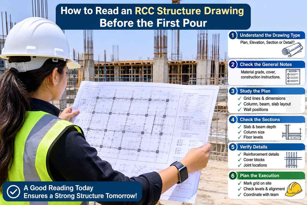
On most sites, the drawing gets a quick look in the morning and then spends the rest of the day folded under someone’s arm. That works until a column comes out 50 mm off its grid, or the bars in a beam turn out to be 16 mm when the sheet said 20 mm. By then the concrete is in, and nobody can fix a pour with an eraser.
Reading an RCC structure drawing properly takes some patience, but it is not complicated. You just have to know what each part of the sheet is telling you and read it in the right order. This guide goes from the basics to the finer checks, so you can stop at whichever level you need.
What an RCC Structure Drawing Actually Shows
RCC stands for reinforced cement concrete, which is simply concrete with steel bars placed inside it. The concrete takes the compression, and the steel takes the tension. An RCC structure drawing shows where both of them go.
It helps to separate it from the architectural drawing. The architect’s sheet tells you how the building looks and how people move through it. The structural sheet tells you how it stands up. It shows the sizes of footings, columns, beams and slabs, and the steel that goes inside each one.
A full set usually includes a foundation plan, a column layout, beam and slab layouts for each floor, staircase details, and a set of schedules. If you still need these sheets prepared, our structural drawings service in Dubai covers structural engineering support and quantity calculation drawings. Each sheet answers a different question, so keep the whole set on the table, not just the one plan you happen to be working from.
Understanding Drawing Sheets, Scales and Symbols
Start at the bottom right corner, where the title block sits. It gives you the project name, drawing number, date and, most importantly, the revision. If your sheet says Rev 02 and the engineer has already issued Rev 03, everything below that is a gamble. Check the revision before you read anything else.
Next, look at the scale. Plans are commonly drawn at 1:100, and details at 1:20 or 1:25. A word of caution: do not measure off the printout with a ruler. Printing and photocopying shift sizes more than people expect. Use the written dimensions and treat the drawn lines as a picture.
Then read the general notes, which many people skip. This is where the grade of concrete, the grade of steel, the clear cover, the lap length rules and the code being followed are all written. Those notes apply to the whole drawing, and nothing else on the sheet will repeat them.
Reading Grid Lines, Levels and Dimensions
Grid lines are the skeleton of the drawing. They are usually lettered in one direction (A, B, C) and numbered in the other (1, 2, 3), and every column is located by where those lines cross. When someone says “column B2”, they mean the column where grid B meets grid 2.
All setting out starts from these grids, so confirm them on the ground before any excavation or shuttering goes up. A small error here travels through every floor above it.
Levels need the same attention. Look for the datum or benchmark the levels are measured from, then check the key ones: top of footing, plinth level, finished floor level and slab top. A level that is wrong by 25 mm is easy to miss on paper and expensive to correct later. Accurate setting out with a total station or a level, done by someone who checks it against the grid, saves a lot of argument later. Our construction site survey checklist covers what to check before a project starts.
Footings, Columns, Beams and Slabs on the Plan
Now read the structure the way the load travels: from the top, down to the soil. The load goes from slab to beam, from beam to column, from column to footing, and from footing to the ground. Reading the drawing in the same direction makes it far easier to follow.
Start with the foundation plan. Each footing has a mark such as F1 or F2, with a size and depth, for example 1500 x 1500 x 450 mm. Check the founding depth and the thickness of the blinding layer underneath.
Columns carry a mark such as C1, with their sizes in a column schedule. The first number is normally the width, and the second is the depth, so a 230 x 450 column is not the same as a 450 x 230 column once you place it on the grid. Beams are marked B1, B2 and so on, again with width x depth. Slabs show a thickness, the direction the main steel runs, and any openings, drops or sunken areas such as toilet slabs.
Reinforcement Details: Bar Marks, Spacing, Cover and Lap Lengths
This is the part that matters most, and the part where most mistakes happen.
Steel is written in short-hand. “8 nos 16 mm” means eight bars of 16 mm diameter. “10 mm @ 150 c/c” means 10 mm bars with 150 mm between their centres. In a beam you will find main bars at the bottom, extra bars at the top over the supports, and stirrups wrapped around them. In a slab you will find main bars in the short span, distribution bars across them and extra top steel over the beams.
For stirrups, look at the spacing carefully. They are normally closer together near the supports, where shear is highest, and wider in the middle of the span. A site crew that spaces them evenly along the whole beam to save time has changed the design.
Then come cover and laps. Clear cover is the distance between the face of the steel and the face of the concrete, and it protects the bars from corrosion and fire. Typical values range from about 20 mm in slabs to 40 mm in columns and 50 mm in footings, but use the figures written on your drawing, because the exposure conditions change them. Lap length is how far two bars overlap when one is not long enough. It is often written as a multiple of the bar diameter, so a 20 mm bar with a lap of 50d needs 1,000 mm of overlap. Laps should also be staggered, not all placed at the same section.
Reading Sections, Schedules and Bar Bending Details Together
The plan tells you where something is. The section tells you what is inside it. The schedule gives you the list. You need all three, and they should say the same thing.
A bar bending schedule (BBS) lists every bar mark with its diameter, shape, cutting length, number and total weight. Use it to cut and bend the steel, and to check the quantity that was ordered. It is worth taking a few minutes to compare it with the section: if a bar mark in the schedule does not appear anywhere on the drawing, or a bar on the section has no entry in the schedule, one of them is wrong.
Take one beam and trace it through all three. Check the size on the plan, then the steel in the section, then the matching rows in the schedule. If the numbers agree, move on. If they do not, stop and ask.
Spotting Clashes and Drawing Errors Before the First Pour
Drawings are made by people, and people miss things. Your job before the pour is to catch them while they are still cheap to fix.
The usual problems are easy to list. Beams are sometimes wider than the columns they sit on. Columns shift position between floors without any note. Architectural and structural sheets disagree on openings, or the MEP services drawings need pipes and ducts through a beam that was never designed for them. Steel at a beam and column joint can be packed so tightly that concrete cannot flow through it properly.
Before the pour, do one last walk with the drawing in your hand:
- Confirm you are using the latest revision.
- Count the bars and check diameters and spacing against the schedule.
- Check cover blocks are in place and the steel cannot touch the formwork.
- Check the lap positions and lengths.
- Check the shuttering dimensions and levels against the drawing.
- Check that sleeves, conduits and embedded items are fixed in the right places.
If something does not match, raise it with the structural engineer before the concrete arrives. Concrete is the one thing on a site you cannot take back, so the five minutes you spend asking are always cheaper than the days you would spend breaking it out.
Conclusion
A good RCC structure drawing does not need to be read fast. It needs to be read in order: confirm the revision, find the grids and levels, follow the load from footing to slab, then check the steel and make sure the sections and schedules agree. Do that before every major pour and most of the expensive surprises never happen.
If the drawing and the site do not match, the drawing is not always the one at fault, but it is always the first thing to check. On renovation work, a building survey shows the condition of what is already standing, so you are not relying on old drawings alone. Ask early, get the answer in writing, and pour only when you are sure.
If you need RCC structure drawings prepared for your next project, talk to the structural drawings team at NES Dubai.
Frequently Asked Questions
What does RCC stand for in an RCC structure drawing?
RCC stands for reinforced cement concrete, which is concrete with steel bars placed inside it to carry tension.
Who prepares an RCC structure drawing?
A structural engineer prepares it, based on the architect’s layout and the soil conditions, and it is usually checked and approved before it is issued for construction.
What is the difference between a structural drawing and an architectural drawing?
An architectural drawing shows the look and layout of a building. A structural drawing shows the sizes of its footings, columns, beams and slabs, and the steel inside them.
What is a bar bending schedule?
It is a table listing each reinforcement bar with its diameter, shape, cutting length, quantity and weight, used to cut, bend and order the steel.
What should I check on an RCC drawing before concrete is poured?
Check the revision, grid and levels, bar sizes and spacing, cover, lap lengths, formwork dimensions and any embedded items, all against the drawing.