
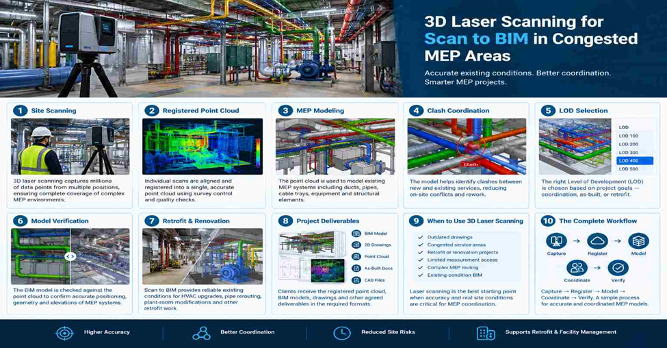
1. Why Congested MEP Areas Are Difficult to Survey
MEP spaces can become difficult to survey when several services occupy the same working area. Plant rooms, ceiling voids, risers and service corridors often contain pipes, ducts, cable trays, equipment and structural elements at different elevations.
- Multiple service routes: Pipes, ducts and cable trays may cross each other at different levels, making it difficult to establish their exact positions through conventional measurements.
- Restricted access: Equipment, structural members and existing services can prevent the survey team from reaching every component directly.
- Limited visibility: A large duct or piece of equipment can obstruct services positioned behind or below it, creating areas that cannot be measured from a single location.
- Outdated drawings: Existing CAD drawings may not reflect modifications made during previous construction or maintenance work, so relying only on drawings can introduce errors into the new BIM model.
- Tight installation clearances: In congested areas, even a small difference in the measured position of a pipe or duct can affect the route of a proposed MEP service.
For these conditions, the survey needs to capture the actual installed arrangement before the BIM modeling and coordination process begins.
2. How 3D Laser Scanning Captures Complex MEP Layouts
3D laser scanning records the surrounding environment as dense spatial data, allowing the survey team to capture existing MEP components without taking individual manual measurements for every pipe, duct or piece of equipment.
- Multiple scan positions: The scanner is positioned at different locations so that services hidden from one position can be captured from another suitable angle.
- Pipe and duct capture: The scan records the geometry and spatial position of exposed pipework, ducts, cable trays, equipment and other visible MEP elements.
- Restricted-area scanning: Scanning can be planned around plant rooms, service corridors and other areas where physical access is limited.
- Occlusion management: Additional scan stations can be introduced where equipment or services block the scanner’s line of sight.
- Complete spatial reference: Multiple scans are combined to create a detailed representation of the surveyed environment that can later be used as the basis for Scan to BIM modeling.
The objective is not simply to collect a large amount of scan data; it is to obtain sufficient coverage for the intended BIM modeling and coordination work.
3. Point Cloud Registration for Accurate Scan to BIM
Individual laser scans need to be registered before they can be used effectively for BIM production. Registration brings the separate scan stations into a common coordinate framework.
- Scan alignment: Overlapping areas between scan stations are used to align the individual datasets into a single point cloud.
- Survey control: Where project requirements call for known coordinates, the scan data can be tied to established survey control for consistent positioning.
- Registration checks: Registration results should be reviewed to identify alignment errors before the point cloud is released for modeling.
- Coverage review: The registered dataset should be checked for gaps, poorly captured areas and locations where MEP elements may require additional scanning.
- Coordinate consistency: Maintaining the correct project coordinate system helps the BIM team position the modeled services correctly within the wider building or facility.
A poorly registered point cloud can affect the position of closely spaced MEP elements, so registration and quality checks are an important part of the Scan to BIM workflow.
4. Modeling Existing MEP Systems from the Point Cloud
After registration and quality checks, the point cloud becomes the primary spatial reference for developing the existing-condition BIM model.
- HVAC systems: Ducts, fittings and major HVAC components can be modeled according to their captured position and geometry.
- Pipework: Existing process, chilled-water, fire-fighting and other pipe systems can be modeled from the visible scan data.
- Cable trays: Tray routes and their relationship with surrounding structural and MEP elements can be represented in the BIM environment.
- Mechanical equipment: Pumps, AHUs, tanks and other major equipment can be modeled according to the project modeling requirements.
- Structural constraints: Beams, columns, slabs and other elements affecting MEP routing can be included so the design team has the surrounding context.
The level of detail should be based on the intended use of the BIM model, rather than adding unnecessary geometry that does not contribute to the project.
5. Using Scan to BIM for MEP Clash Coordination
A scan-based BIM model gives the project team a way to review proposed MEP work against the existing physical arrangement before installation begins.
- Pipe-to-duct conflicts: Proposed pipe routes can be checked against existing HVAC ducts and other services occupying the same space.
- Cable tray coordination: New cable trays can be reviewed against existing pipework, ducts and structural elements before the installation route is finalized.
- Equipment clearance: The model can help the team review the space required around equipment for installation, operation and maintenance.
- Ceiling coordination: In congested ceiling spaces, proposed MEP routes can be reviewed against the actual positions of existing services.
- Plant-room coordination: New equipment and service connections can be assessed against the existing arrangement before physical modifications are carried out.
This approach allows coordination issues to be identified during the design stage instead of waiting for the installation team to encounter the conflict on site.
6. LOD Selection for Congested MEP Scan to BIM Projects
The required Level of Development should be established according to what the BIM model needs to achieve. A coordination model and a detailed retrofit model may require different levels of information.
- Coordination requirements: If the model is primarily being used for clash coordination, accurate geometry and positioning of the relevant MEP services are the main priorities.
- As-built requirements: An existing-condition model may need to represent the installed arrangement closely enough to support future design and documentation.
- Retrofit requirements: Retrofit projects may require additional detail around equipment, connections, service interfaces and areas affected by the proposed modifications.
- Model scope: The project team should define which architectural, structural and MEP elements need to be modeled before production begins.
- Deliverable requirements: The required software, file format, model structure and level of detail should be agreed before scanning and modeling commence.
Defining these requirements early prevents the BIM team from spending time modeling details that have no practical use for the project.
7. Verifying the BIM Model Against the 3D Laser Scan
The completed BIM model should be checked against the original point cloud to confirm that the modeled elements correspond with the surveyed site conditions.
- Pipe position checks: Existing pipe routes can be compared against the point cloud to identify noticeable differences in location or elevation.
- Duct verification: Duct geometry and positioning can be reviewed against the captured scan data, particularly in areas with limited clearance.
- Equipment checks: Major equipment can be checked to confirm that its modeled position and overall geometry correspond with the surveyed condition.
- Elevation checks: MEP service elevations can be reviewed where vertical clearance is important for coordination.
- Model quality control: Areas where the model does not adequately represent the point cloud can be identified and corrected before final delivery.
This verification step is particularly useful for retrofit projects because the BIM model is being developed from existing physical conditions rather than relying entirely on historical drawings.
8. Scan to BIM for MEP Retrofit and Renovation Projects
Retrofit projects often involve modifying existing MEP systems while keeping parts of the building and its services operational. This makes accurate existing-condition information important before new work is designed.
- HVAC upgrades: Existing duct routes and equipment locations can be captured before replacement or modification work is planned.
- Pipe rerouting: Existing pipe positions can be reviewed when planning new connections or rerouting around other services.
- Plant-room modifications: Scan data can document the available space around existing equipment before new equipment is introduced.
- Ceiling renovations: Existing services above ceilings can be captured before new layouts or architectural finishes are developed.
- MEP replacement: Existing equipment and connection points can be documented to support replacement planning.
- Brownfield modifications: Existing industrial facilities can be surveyed without depending entirely on drawings that may no longer represent the installed condition.
The workflow can therefore move from 3D laser scanning → registered point cloud → Scan to BIM → MEP coordination → retrofit design.
9. What the Client Receives After Scan to BIM
The final deliverables depend on the project scope, but the survey and modeling package can include both the captured scan data and the resulting BIM information.
- Registered point cloud: A coordinated point-cloud dataset containing the surveyed spatial information can be supplied in the agreed format.
- BIM model: The existing building or MEP systems can be modeled according to the agreed LOD and project requirements.
- MEP model: Relevant pipes, ducts, cable trays, equipment and associated components can be included where they fall within the defined modeling scope.
- 2D CAD drawings: Plans, sections and elevations can be generated where CAD documentation is included in the project deliverables.
- As-built information: The model and drawings can provide a current record of the surveyed physical arrangement.
- Point-cloud reference: The original scan data can be retained for future verification, additional modeling or design coordination where required.
The important point is that deliverables should be agreed before field scanning starts, because the required scan coverage and modeling detail depend on the final project use.
10. When 3D Laser Scanning Is the Better Starting Point for MEP BIM
3D laser scanning becomes particularly useful when the project involves an existing building or facility and the available documentation does not provide enough confidence for accurate MEP coordination.
- Outdated drawings: When existing CAD drawings do not match the current installation, scanning provides a direct record of the surveyed condition.
- Congested service areas: Plant rooms, risers and ceiling voids with multiple overlapping services can benefit from dense spatial capture.
- Retrofit work: When new MEP systems need to connect to existing services, accurate information about existing routes and elevations can reduce uncertainty during design.
- Limited measurement access: Scanning can capture large amounts of spatial information from planned scan positions where direct measurement of every component would be difficult.
- Complex MEP routing: Closely spaced pipes, ducts and cable trays can be documented together so their spatial relationships are available for BIM coordination.
- Existing-condition BIM: Where the project requires a BIM model of an existing facility, the point cloud provides a measurable reference for model development.
For congested MEP environments, the practical workflow is:
Capture → Register → Model → Coordinate → Verify
The purpose is not to create a BIM model simply for documentation. The aim is to give the project team reliable existing-condition information that can be used for coordination, retrofit planning and design decisions.
Surveying Services by NES Dubai
Northern Engineering Surveys L.L.C. (NES) provides reliable surveying services in Dubai, including 3D Laser Scanning, Topographic Survey, Volume Calculation, Land Surveying, and Total Station Survey.
Contact NES Dubai for your surveying requirements.